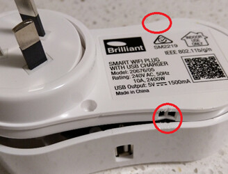
Brilliant Lighting Smart WiFi Plug with USB can be purchased from places like Officeworks, Bunnings etc for around $19-20 see here and then flashed with an alternative firmware such as Tasmota. Below is the steps I took to modify and flash the device.
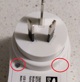
- Use a small screw driver or knife to remove the plastic plugs on the back so you can get to the screws underneath then pry the case open in the locations as shown.
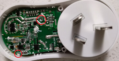
- Once inside there is two smaller screws, undo them to release the board from the chassis.
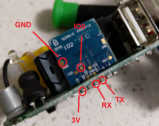
- Cut 5 small wires (I used CAT cable) and carefully solder them onto the board in the following locations.
-
Carefully connect each of the wires to their locations on the FT232RL FTDI USB 3.3V 5.5V to TTL Serial Adapter Module for Mini Port flashing tool then plug the FTDI into your Windows PC. If you don’t have this tool you can buy one here also dupont cables can be located here. Note: IO0 needs to be grounded to the flashing tool on boot to enter flashing mode. Also, RX on FTDI goes to TX on chip and TX on FTDI goes to RX on chip.
-
Download and open ESPEasy you can find that here also @markus latest Tasmota Hubitat firmware here.
-
Flash the device and don’t forget to ground the IO0 pin during boot to put the chip into flashing mode. Select the COM X port then find the Tasmota Hubitat .bin file. Once flashed reboot the device but unplugging and plugging it back in for it to exit flash mode.
-
The device will create a Tasmota XXXX access point. You will need to connect to that and go to the IP 192.168.4.1. Here you will configure your WiFi details and select save. Your device will reboot again. You will then need to check your router as to determine its allocated IP address on your local network. Note: I recommend a static IP address for this as you do not want it to change.
-
Type your new IP into your browser, once you have logged onto the device’s Tasmota web portal select configuration and then configure module. From the drop-down list select generic and again select save and it will reboot. Once rebooted go back to the same location and apply the below settings save.
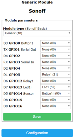
- Finally you will need to configure the device into Hubitat. You can find out how to do this and more over in @markus thread by clicking on the link at bottom of this post. Thanks again for reading and any questions don’t hesitate to reach out below or within the community.
**Additional temperature and humidity requirement then read on
-
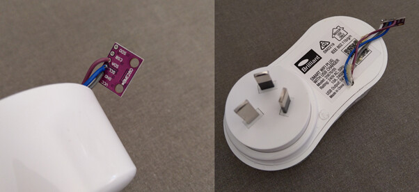
Purchase BMP280 temperature and humidity sensor from here.
-
Solder the sensor to the locations I highlighted in step 3 above.
RX - Purple – SDA
TX - Blue – SCL
3v – White
GND – Grey
- Finally you will need to configure the device into Hubitat. You can find out how to do this and more over in @markus thread by clicking on the link at bottom of this post. Thanks again for reading and any questions don’t hesitate to reach out below or within the community.