That is very cool, I assume since it is using radar tech, it will actually be able to detect the occupancy of the room versus just motion detection of PIR which would be great. But at the same time, I wonder how well it would work as a battery powered device since I assume it is basically always on sending out waves and getting a response which sounds terrible for battery life.
Ultrasonic sensors are great, IIRC that is what most cars use for parking assistance and even autonomous parking, but all of the ones I know of are super short range, like in the 1 meter at most range which doesn’t seem like it would have a lot of applications for HA.
FYI, Amazon recently came out with a new voice for Alexa (I think called Ziggy?) that is a male variant, and it is actually pretty decent. I wonder if your dog would have the same reaction to that.
Not sure if you and markus got the same ones I’ve been using, or how you guys wired yours up, but i get about 5m on 3.3v and 9m on 5v
Yes and no… if paired with a servo motor you can create an radar style display and readout determining how far away objects are and if they are moving etc but on their own they are best for distance sensing.
I use them for automatic doorbells, package detection, and i have stuck them in my cars bumpers which alert me if i get closer than 3 inches to anything, which is really handy for parking in tight spaces.
Not sure if you’ve discussed this option, but would some kind of Bluetooth detection for smart watches be an option for additional presence detection? I’ve grappled with trying to detect my tile device without any success, so not sure if it would work any better with a watch or other Bluetooth device…
We’ve been messing with BLE as well. It’s not as interesting. connected it to my fitbit through mqtt. It wasn’t all that great and I felt that it fell a little short, actually. I have the flows and the board information if you want it. I’d have to find the other stuff. @jchurch and I worked on it together.
I’m struggling just to work out the mac address of the tile, so haven’t even got to any automations at this stage. It shouldn’t be that hard, but thought maybe other devices or other software may have yielded a better result and could have helped in your situation. Shame…
Reach out to @jchurch . He’ll have some insight for you. It works. There was an issue, but I can’t remember exactly what that was, but we haven’t had time to work it out yet.
Also an issue with BLE is that is it relatively long range, and I feel like it would have issue determining which exact room you are in, unless you had multiple receivers and compared their signal integrity, but that is a whole other ball game. Now if all you are trying to do is general presence for geofencing, then that might be great, especially if you want more granular control than WiFi phone detection. Here is a post to a thread I have been following but never got around to implementing:
@sburke781 yeah I have configured BLE using Wemos D1 mini ESP32 and it worked. As to resolve the issue @Cjkeenan mentions you can tune it to only do something with things that are close by and ignore the rest but as he mentions you’d need them in each space.
Anyways I had it running using OMG here but word of warning when I ran this I started experiencing dropouts from some of my Zigbee devices I pulled it out and it immediately went away. It was weird though just some sensitive devices like my Schlage doorlock and Samsung button the Xiaomi Aqara’s didn’t care at all. Anyways good luck it’s a fun project.
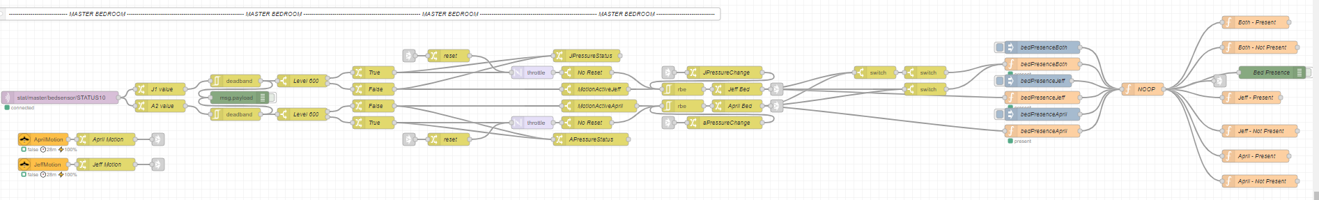
You have sent me down a rabbit hole with this one but as mentioned I tried the load cell method and been unhappy with its consistency. So I’m giving this a go! Your instructions have been excellent so was able to knock up a POC quitely quickly once the pressure sensors arrived in the post.
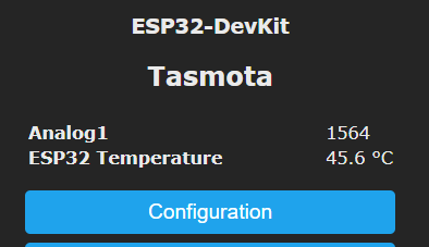
I have everything hooked up for testing but wanted to understand what outputs you get in your Analog readings. When not loaded I’m seeing fluctuating values between 1300 - 2400:
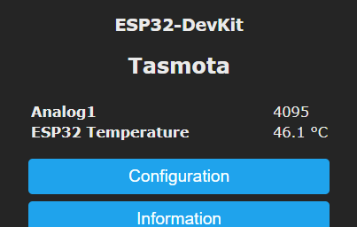
When under load, I see the value max out at 4095:
I have a resistor as per your diagram but wondering what you found once under the mattress as I have tested this to just registers 4095 without showing changes. It does sometimes dip slightly but overall it behaves as if it is under full load.
Any suggestions or did you find the same? I had a look at the ADCParam commands but they dont seem to be used to calibrate a std analog input…
That’s great! I’m happy you tried it. I reached out to Markus as I’m driving. I’m getting 0 readings when under the mattress. Perhaps you might need a different resistor? Or is your strip getting pressure at the solder? I had this. I redid my solder making sure it was straight. I’m not a pro at it.
@BlackCatPeanut The expected reading would be 0, just like April I have 0 even under the mattress. However, any bends or pressure to the solder joints could cause erroneous readings.
What’s the resistor value you’re using?
EDIT:
Just a little bit of extra information, this is a essentially a voltage divider, the ESP32 reads a voltage between 0 and 3.3V, 4095 is 3.3V. When there is no pressure you should be at 0V, or at least very near.
This is not the exact strip model, but it gives some additional information on page 3: Combined.pdf (adafruit.com)
Sorry, deleted my previous comment by mistake… I was going to say that I have counted out the picture a few times to figure the GPIO 32 & 33 as I’m importing your template.
I’ll move onto soldering the pads together to remove the crocodile clip pressure and see if that helps. Thanks for the prompt responses @april.brandt and @markus
Aha, I have just found that screen you showed above - Configure Template. #AlwaysLearning - I was checking out the template docs on Tasmota website Thanks again!
Any reason you are specifically using this model btw? The NodeMCU’s seem to be a much better deal and from a cursory overview seem to be basically the same spec, minus the Bluetooth and processor speed:
Markus and I worked on this together. Markus already had one, so I Matched it. No real reason. I’m sure any board would work. We preferenced Tasmota on this project.
EDIT:
I also wanted to add that we used the bluetooth board because we considered BLE for the project as an extra check considering phones would be present in the room charging as well. Since BLE is still a bit unreliable in these cases, we hadn’t broached it. And we may not.


 Thanks again!