It’s been rather quiet around here lately and I realized my latest project might actually be of some legitimate interest so I decided I’d share it with you and create a small tutorial.
So some background before we get into it. 3 days ago while cleaning what I lovingly refer to as the junk room I came across an old Uno clone board and some old parts from an arcade machine in the mess. After I finished cleaning I decided to see if the board was still good. It was… next thing you know 30 minutes has passes and wouldn’t you know it… I’d built an arcade style controller for my PC.
Now here is where things get interesting… When double checking a pins functionality I discovered that an ESP version of the clone is available dirt cheap… Well of course we all know I decided I wanted to try out creating my own Smart device just for the fun of it. I hopped on amazon and ordered a 2 pack of the old Wemos D1 uno clones for 15.99 from amazon, which arrived yesterday.
Well after a bit of tinkering I had a DUH moment and remembered that these boards support TASMOTA and are VERY EASILY flashed with it. 5 mins later and I have one of my new boards flashed via tasmotizer and wired up, 5 minutes later i have it fully integrated into my node-red.
I did not originally plan to make this into a tutorial so i do not have pictures for the boring parts, aka building the enclosure, soldering wires etc.
So here we go a Tutorial for Making your own Tasmota based IOT button device!
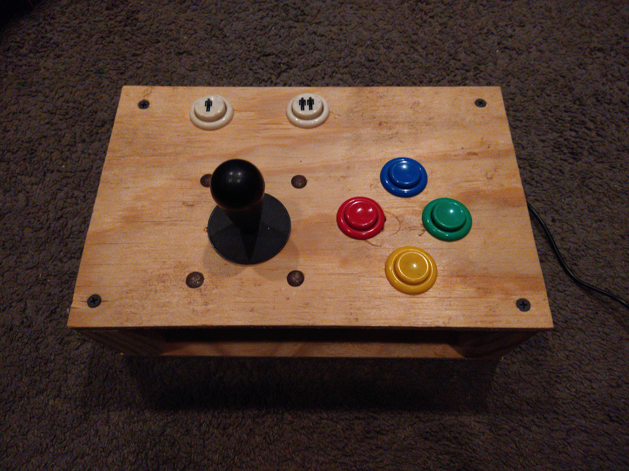
Presenting the Automation Arcade Controller 2000 Alpha .2 ![]()
Although I originally made this to be a usb controller this tutorial will only focus on the IOT device side of things, If there is enough interest I will do a follow up on how to create your own HID-USB arcade controllers. Here are the boards i am using side by side.
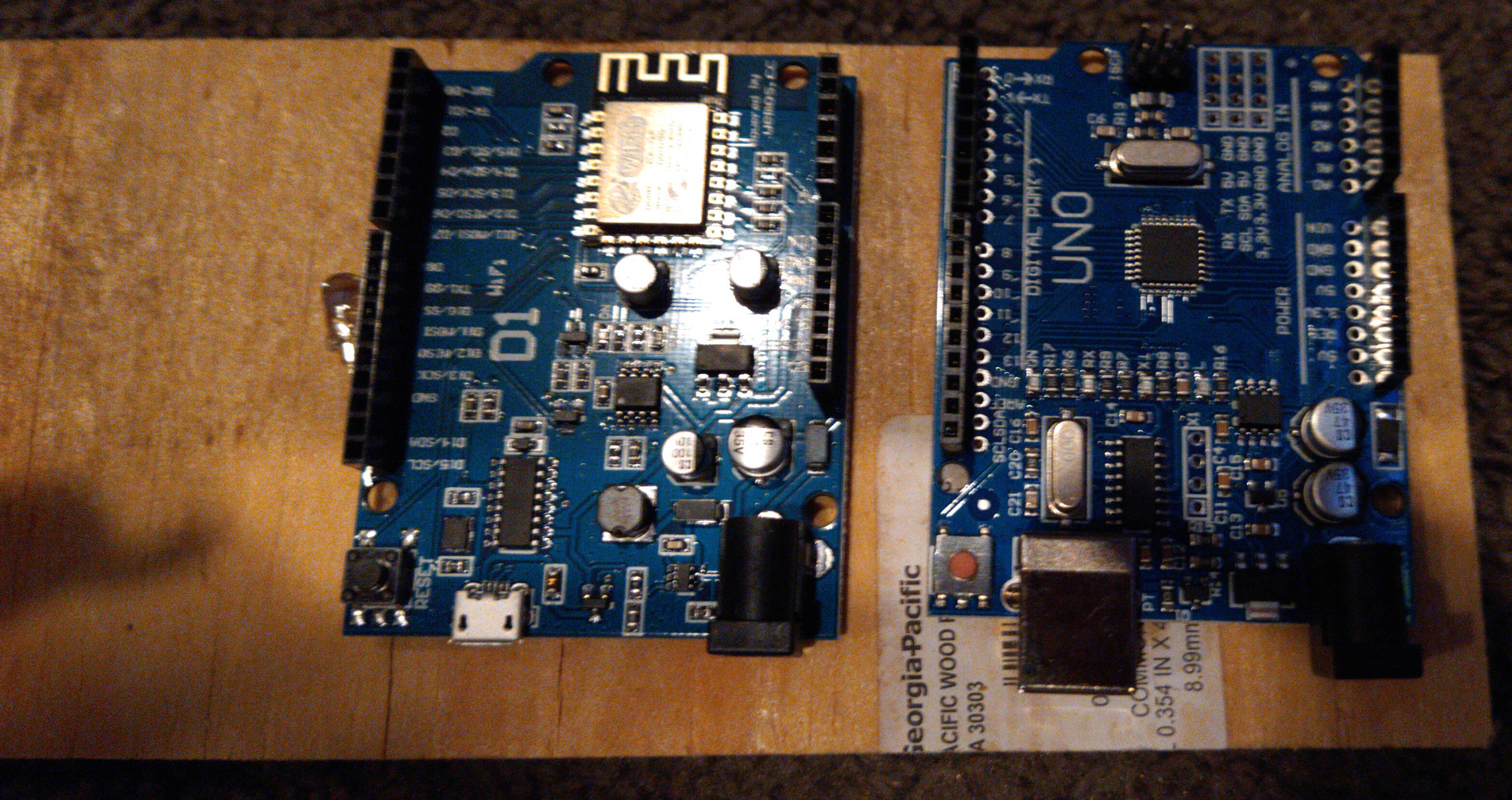
Left is a Wemos D1 Uno, at the back of the board you can see the esp wifi chip. ~8.00
On the right is the Arduino Uno clone, which does not have wireless functionality. ~4.00
The first thing we will need to do is download and install the usb serial driver we need to be able to write to the board. Links and instructions for various OS can be found here :How to Install CH340 Drivers - SparkFun Learn
Once our drive is install its time to download and run tasmotizer. This is a standalone exe (nothing to install) that will be used to install the latest version of tasmota onto our device for us nice and painlessly ![]() (I will cover advanced install methods and platforms later if their is interest)
(I will cover advanced install methods and platforms later if their is interest)
https://github.com/tasmota/tasmotizer/releases/download/v.1.2/tasmotizer-1.2.exe
Now its time to run tazmotizer. Click on the com port drop down and make note of all the listed ports. Now plug your D1 into your computer via the usb cable. DO NOT GIVE IT AC POWER! Click the com port list again and you should now see a com port listed that was not there before. Select it from the list. If you wish to save the original firmware that comes on the board check save original firmware and select a flash size of 4MB. Under Select Image select release, and make sure tasmota.bin is selected in the dropdown. Check both self-resetting device and erase before flashing. Refer to the image to confirm your settings match. Press tasmotize and wait for it to finish. This process will take anywhere from 3-10 minutes depending on if you back up the flash.

Now that the process has completed your board will reboot into AP mode. You could connect with your phone to that AP and use the web UI to configure your wifi settings but theres a faster way ![]()
Return to your tasmotizer window (if you closed it thats ok just run it again and select the same com port as before) and select Send Config. That will give you this handy little window.
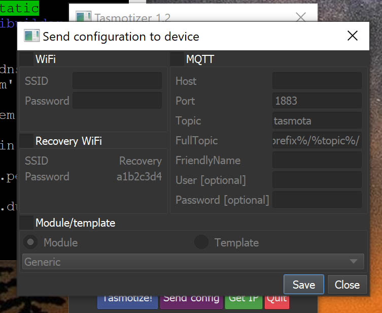
Check the wifi button and enter you network info. I advise also setting up a recovery Wifi entry with the SSID of Recovery and no password. This way should you ever change your network setup and forget what your old ssid and password you can create an SSID of recovery with no password and regain access to your devices without having to reconnect them to your PC via cable.
If you use MQTT then also check the MQTT box and fill out the details as you see fit (we can do another tutorial on MQTT if there is interest, in the meantime google is your friend if your curious)
Check the module/template box and make sure module and generic are selected. Press Save. Press Close.
Wait a moment of so for your device to reboot itself and connect to your network, then press the Get IP button in Tasmotize. Presto this is your devices auto assigned IP. If you type this into a web browser it will take you to the tasmota web interface for your board. Let’s go ahead and do that now.
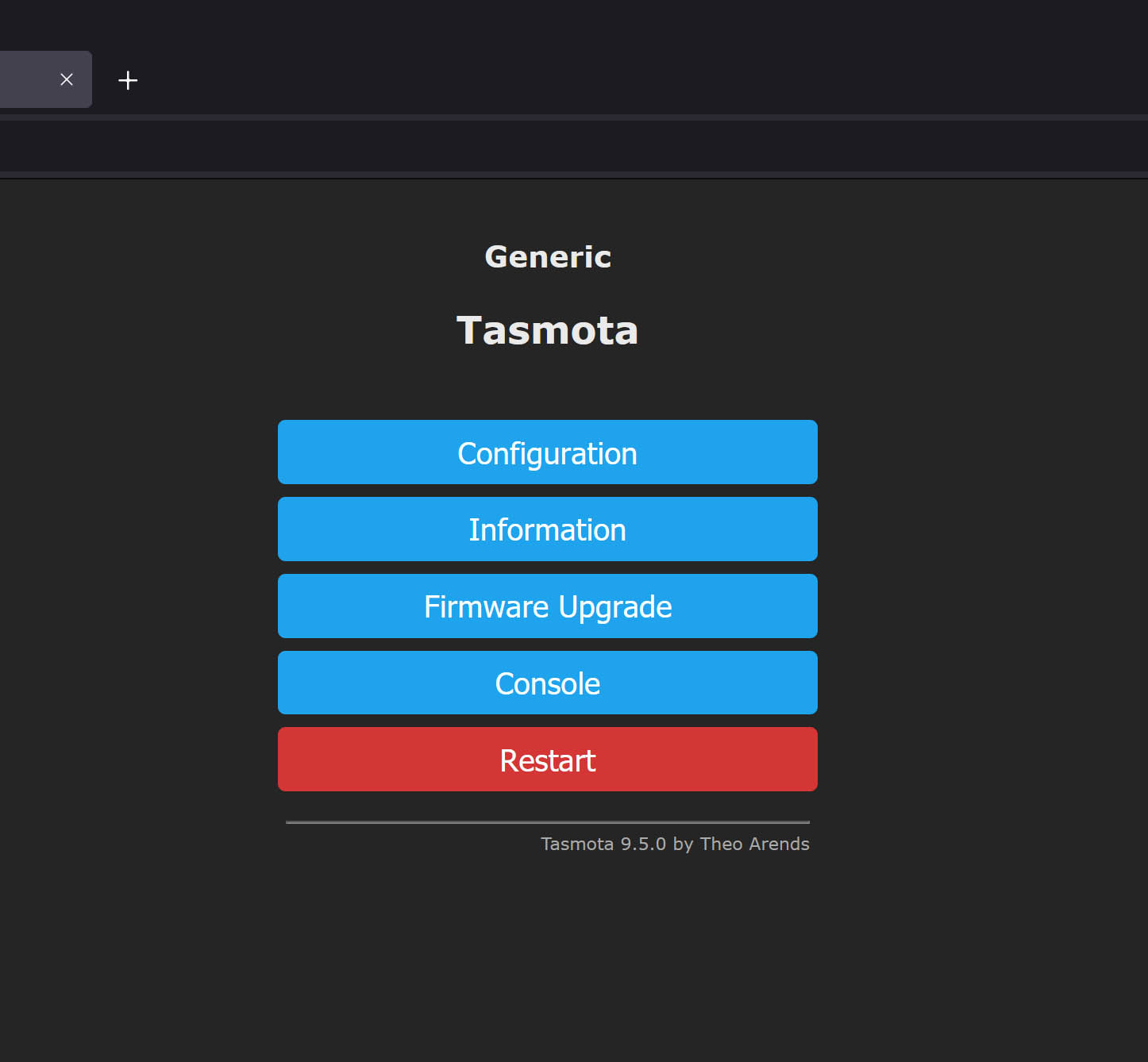
Not the most attractive color scheme is it? Don’t worry you likely won’t see this interface much if at all after the initial setups complete, and if you decide you want to use the interface for controlling things later on you can adjust the colors to your hearts content, though that is beyond the scope of this basic tutorial.
Let’s go ahead and click configuration and then configure module. Since I am only covering using digital pins to hook up buttons lets just go ahead any copy the following settings onto your board. These settings will configure 8 of the digital pins on your D1 board to read the input and react in the way a button would. (youll notice a TON of different ways you can use these pins and we will cover more of these in future tutorials)
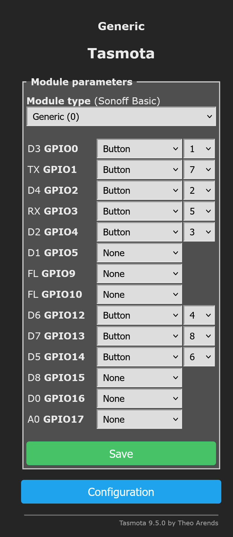
Now that yours matches mine go ahead and hit save and wait for the board to reboot. Once it has rebooted the web UI will return to the main screen. From here lets press the button marked Console. On this screen we need to type the command “setoption1 1” and press enter, then “setoption73 1” and finally restart 1 and enter. setoption1 1 disables the config reset on button hold for 40 seconds, 73 decouples the buttons from relays, and restart of course restarts the board so the settings take affect. More details on Tasmota commands can be found here: Commands - Tasmota
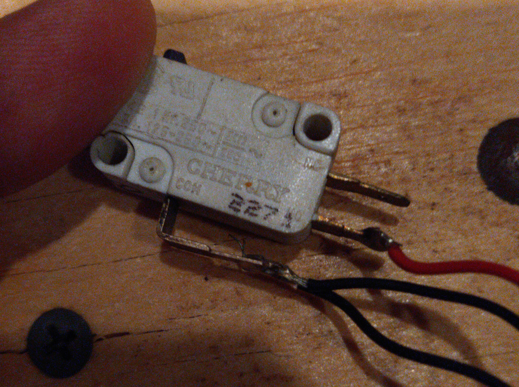
At this point we can move onto setting up our buttons. The button style you are using will determine how you need to wire the button. Check the spec sheet and it should tell you which pins are ground and which are current. Most buttons will have 2 terminals for one or both connections. For our purposes we will be using a simple arcade button which functions like your standard light switch. When pressed it completes a circuit when released it breaks the circuit.
As you will see in the following images, that is because buttons are really just switches you push instead of flip to connect.
Now lets start wiring up a button to test with. Please note this is only for using digital pins, 1 button per pin, it is possible to use the analog pin and connect a very large number of buttons through it alone, but that is a bit more advanced than our goals today.
Start by connecting one wire to the ground terminal of your button and another different wire to the current(+) terminal on your button.
Repeat this process for all remaining buttons. Now connect all of the buttons ground wires to each other, leaving a free ground wire at the end of the chain.
At this point your buttons should be wired up like this.
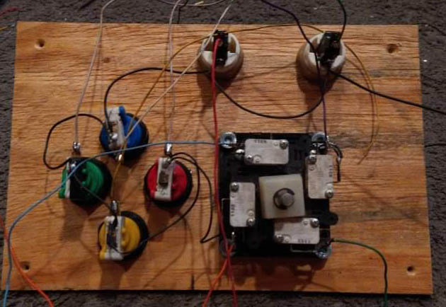
Once you have all of your buttons ground wires connected together locate any ground pin on your board and connect the free end of your buttons ground wire to this pin,
Take the wire coming from each button and connect it to its own digital pin.
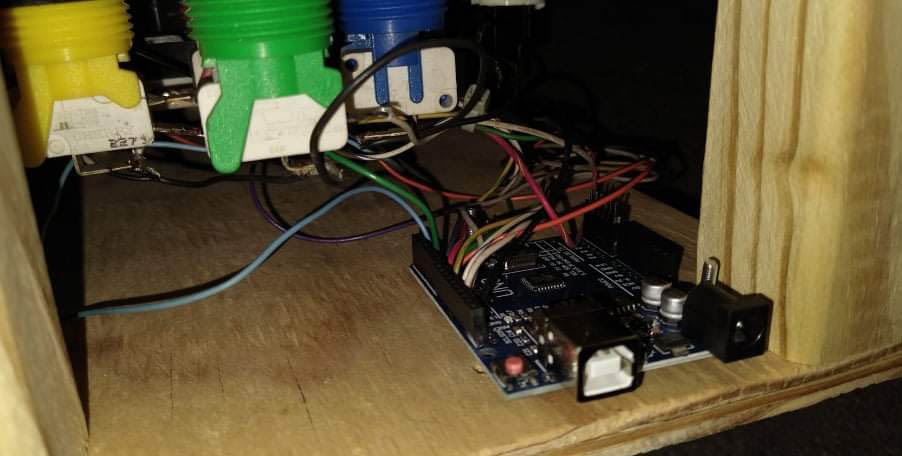
Now lets go back to the console window we left open in our browser. Press one of your buttons and you should see a message appear in the console window. with the button number and the type of button press.
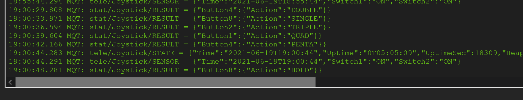
If you have any buttons that don’t register try moving them to a different digital pin until you find one it registers on. With this configuration the first 10 digital pins are used, skipping the 3rd providing a maximum of 8 buttons and 1 switch/relay/misc.
Oh yeah with this configuration you aren’t limited to single double and hold presses, you get all the way up to penta (5) quick presses registering to use as a trigger ![]()
So at this point you should now have buttons you can press that register in the web interface and possibly your MQTT server.
This is where things get really fun. Depending on your preferences you have multiple control options. You can use ANY control solution capable of controlling a tasmota device. That means HE, HA, ST, NR, mobile apps, etc.
In my case I am using an MQTT server interfaced with node red to control things. As this was originally intended as a gaming controller I didn’t have any automations planned to go along with this spur of the moment tutorial so I tied the controller to a rooms lighting.
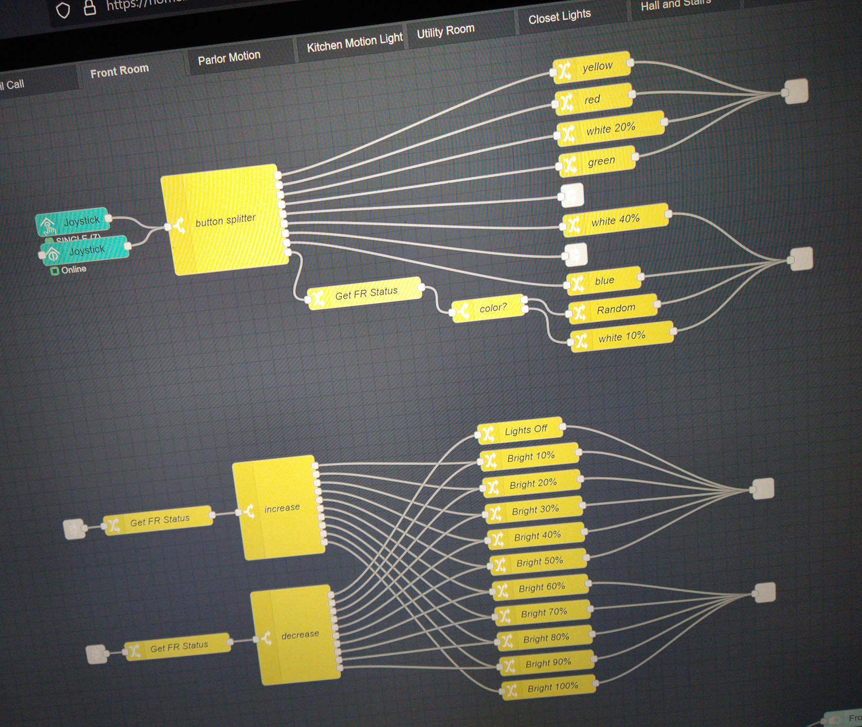
Colored buttons make the lights that color, the 1 player button makes the lights go into “party mode” where they do the color fades, or shift it back to normal white from any color or patter, the up and down joystick axes turn the brightness up or down, and left and right on the joystick are quick shortcuts to white light at different %s.
Hopefully this is easy enough to understand, and if there are any parts you guys need clarified or more pictures for just let me know and I’ll be happy to revise and add ![]()
Now go enjoy the thrill of having made your very own smart IOT device and try not to fall to far down the rabbit hole too fast… Your quickly going to realize you can make any smart device you could have ever dreamed up, and at a reasonable cost too! (Oh and just wait until you discover we can also get these type of boards that are zigbee or zwave based)
