Christmas Light Sharing :)

Though I am not done, I was also told I will never actually be done, so here are a few short clips from of my house taken about an hour ago. Sorry for the poor audio/video quality, turns out my cell is the best camera I have these days :rofl:

That being said hope you enjoy one of my other hobbies :slight_smile:

8 Likes

Very nice work. With so much light/sound, I guess no one will be able to sleep inside until 2024… :wink:

1 Like

Awesome job @RRodman , all I can think of is the movie Deck the Halls… :slight_smile:

1 Like

the music is actually being broadcast on an empty radio frequency that onlookers can tune in to and listen. As for the light, I think that he’s negotiated a cutoff time for them.

1 Like

In case anyone is wondering how that fits into smart home automation Rob has programmed and built his entire setup from the ground up. I’d say that qualifies.

1 Like

Well as April already mentioned the audio is broadcast over the air (FM) so it doesn’t disturb anyone, and as far as the lights go… I’m only running at 15% brightness in the video, all the neighbors love the lights, and I haven’t had a single complaint even when i go out at 2am and turn the brightness up to 50% and test out new sequences hehe.

Actually the only complaint I have had so far is that they don’t stay on longer each night!

It’s also integrated into and controlled by NR running on CORE. Automatically fires up at dusk, turning everything on, setting proper modes, closes all the blinds, turns off any external lights that are on, starts the playlist, and monitors the status of the show to alert me if anything fails (And automatically cut the power) and also let me know when someone is outside watching and choosing what song they want to hear/see next.

Def qualifies as automation related, even though it was 100% just a post to show off what has had all of my attention lately. :wink:

1 Like

Very nice. Specifically what hardware are you using to drive the lights?

1 Like

Beautiful! I like the sobriety of it all.

:slight_smile:

I am using a bunch of esp8266s and a few dig-quads (esp32s with ethernet hats) running WLED to drive the leds, FPP running on a Pi4 to handle the synchronization and broadcast of the music and sequence data to the radio transmitter and all of the WLED instances.

Power is being handled by a 24v PSU, and a bunch of buck convertors.

1 Like

Do you have some photos of the esp → LED strip connections? I am always struggling to get this solid,

Depending on what you personally are trying to do pictures of my setup may not be of much use to you.

Basically in my setup each esp8266 would have 3 wires in total connected to it. 1 Power and 1 GND supplying the board, and 1 data line running out to the leds. The LEDS get their power from their own power supply. A GND is tied between the power supply used for the LEDS and the one used for the ESP.

In general you DONT want to power the ESP via the USB port and then power the lights off of the ESPs V and GND. You can but even the highest quality ESP is only going to be able to supply a about 1.2A, which will limit you to around 20 leds at full bright white, though if you use a program with current limiting (like wled) you can usually push about 100 leds at a decent brightness for most applications.

That tends to look something like this (not my image). The resistor isn’t always needed, it really depends on the environment, noise, wire size, distance etc, and is used to help smooth noise out of the signal ensuring clean peaks and valleys, and the 2 standard values used are 33 and 249.

The board would also look like this if using the same or different external power supplies for the board and led strip,

The only time the connections to the board wouldn’t look like this in a basic setup for driving addressable leds would be if using USB to power the board, and a different power supply for the LEDS, in that case there would NOT be a power wire connected to the board. In ALL cases the GNDs of the supplies WILL be connected.

If your interested in more in depth info I should be able to get a few links together for you in the next couple days :slight_smile:

1 Like

Ive recently stumbled down the adressable led rabbit hole. Quite deep indeed. Ive been playing with pixelblaze myself but still lots of overlap here.

I would appreciate any and all insights. Tip and tricks. Weatherproofing. Different led types your using (this topic alone can take many hours to sift throug). Power injection advice. How best to manage wire runs and splices.

Thata not too much right? :imp:

Pictures of course are amazing.

Again your setup looks amazing. Thank you for sharing.

And a very deep rabbit hole it is… especially once you realize a LOT of the info out there is not at all scientific and basically this is what I did that worked for me but I don’t know why, which evolved into this is just what everyone does cause it works, with generalized explanations why.

Now before I say what I am doing, I will say it is far from what is the “normal” setup, and flies against a ton of the advice and best practices you will come across online. I also likely have the cheapest “cost” for a show of this size, as I am a major penny pincher and hate spending money when not needed.

I am using ws2812 5v RGB pixels, and some of the equivalent 5v strips. Pixels are direct from Ray Wu, and strips are btf lighting.

Using a single 24v power supply to run everything and avoid voltage drop issues over longer power line runs. I then use 3A buck convertors on the props to drop the voltage down to 5V. I design my stuff to be able to run all three channels at the same time at 100% brightness, though i never turn it up past 20, maybe 30 if its a foggy night, anything above that is just too bright.

That means for every 50 lights I have a buck convertor. The 2812 specs list a max draw of 20ma per channel for full brightness, of 60ma per pixel. Buck Convertors can be gotten for under .10 a piece in bulk. Power injection really comes down to 2 factors. How bright you want to be able to run your lights, and preventing discoloration from voltage drop within the string itself.

The higher the voltage and the shorter the wiring between the individual pixels the more leds you can power before needing to inject. There is really no correct answer sadly, other than as often as needed for your preferences.

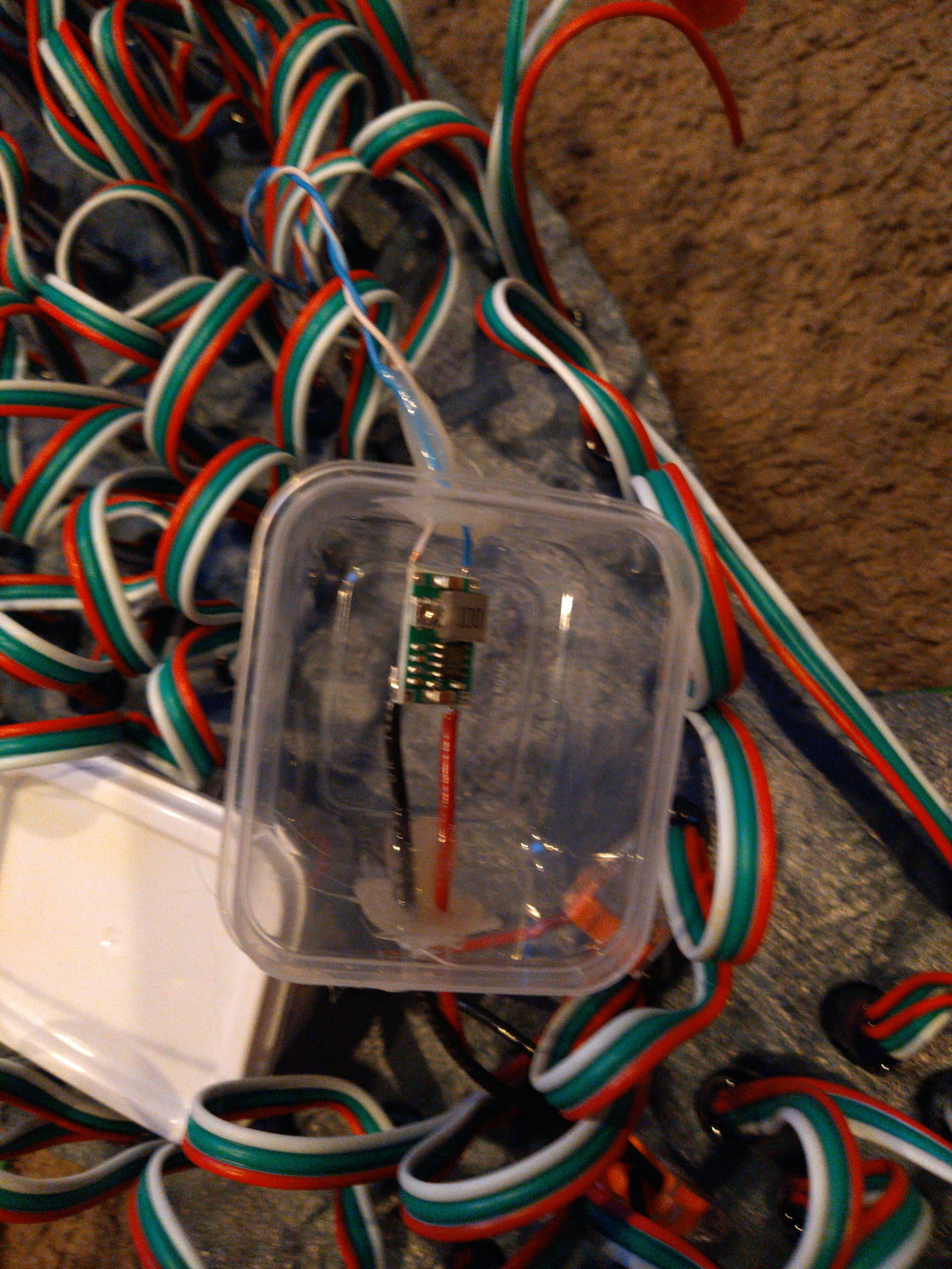
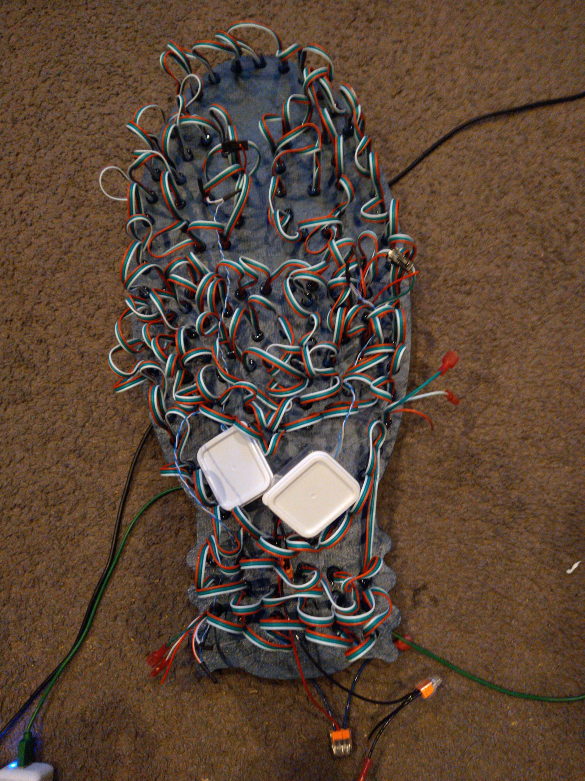
For the few controllers that are out in the yard and not protected, and the buck convertors, I am using the cheap 10 pack of mini tupperware containers from the dollar store. Melt a hole big enough for you wires on two sides (PWR+GND X 2, IN and OUT) controller goes inside, bit of hot glue to seal up around the wires and your good to go.

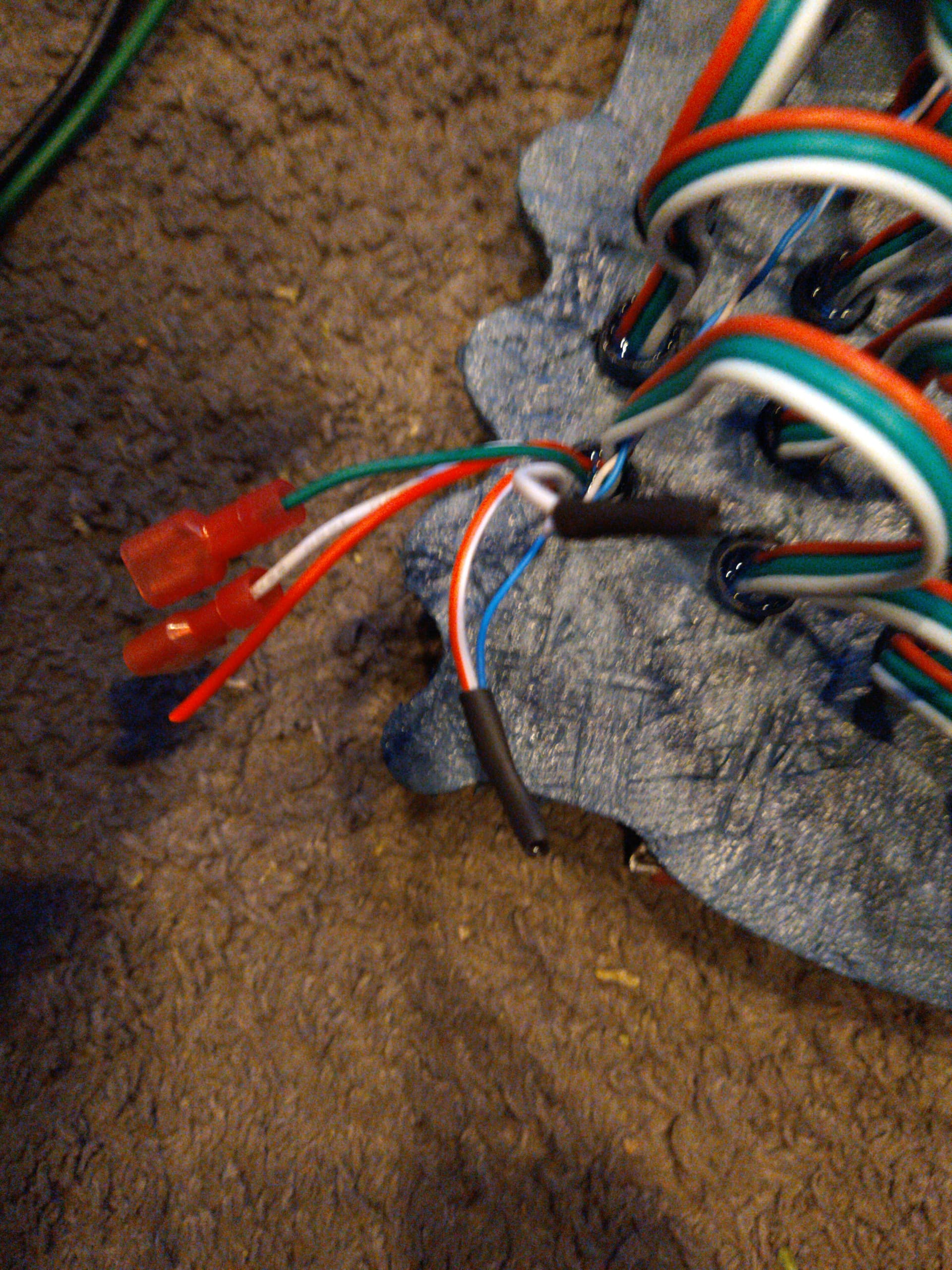
I am using standard covered spade connectors for all of my connections with just a touch of dialectic grease to keep them water tight.

Because I am using 24v at a lower Amperage than what would be needed if the power supply was 5v, voltage drop and load on my wires is much less of a concern.

Voltage drop for a 5v line with 48A on a 14 gauge wire over 10 feet is over 50%, leaving you with less than 2.5V at the end of that 10 foot run.

In comparison (or contrast) Voltage drop for 10A at 24V over 10 feet is only a 2%, leaving you with 23.5V at the end of 10 feet, and even at 100 feet out drop is only 22% leaving you with about 19V at the end of your run. Plenty to buck convert down to the needed 5 and drive all your lights.

Also ignore anyone telling you that you can only drive 200/400/600 leds to a port. Look up the data rate of the lights you are using and calculate the actual limits yourself. ws2812 can reliably push between 800-820 leds to a single data port at 40fps!

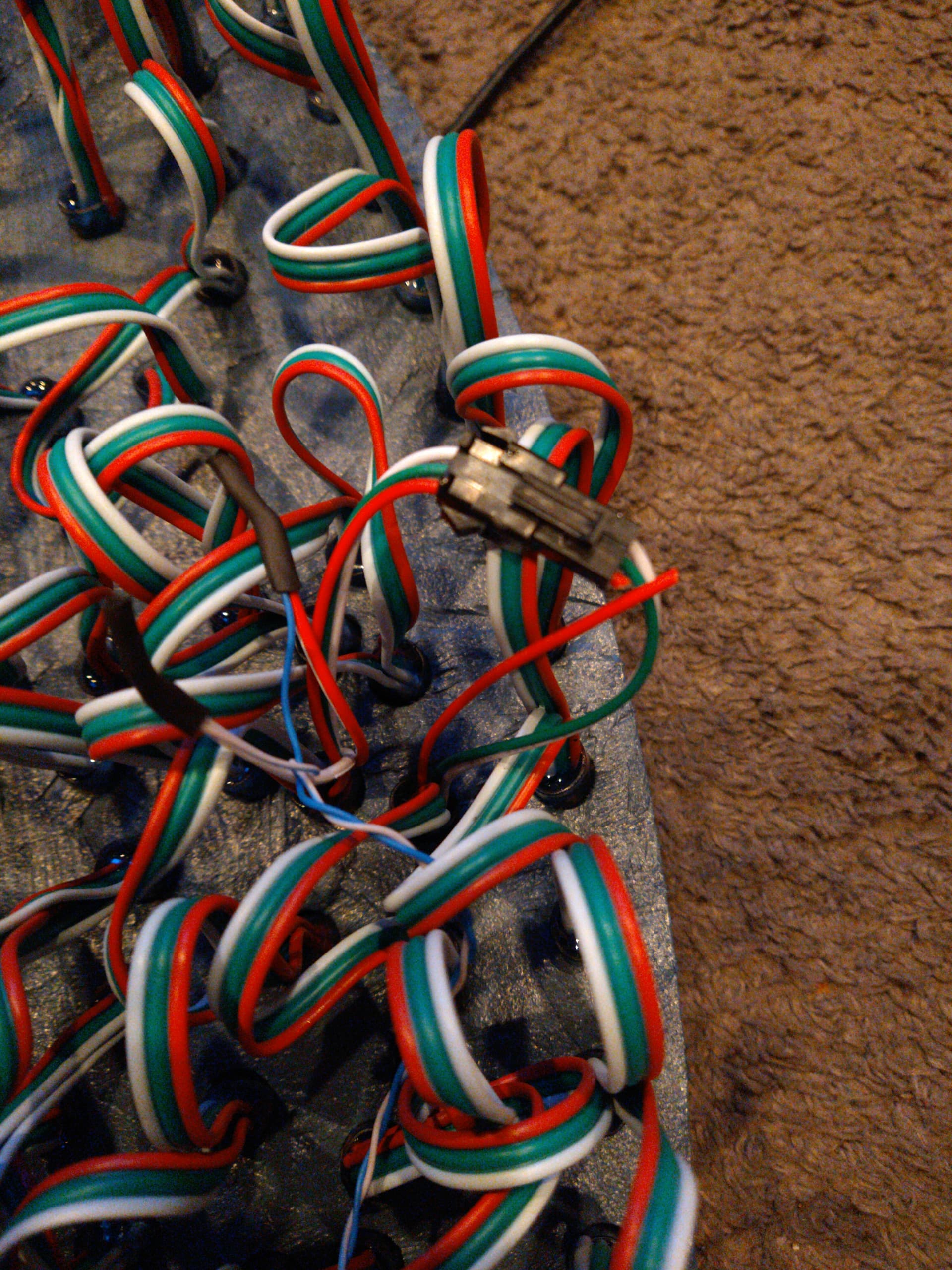
The best way I have found to manage wiring is using zip ties, and daisy chaining as many props/strings together as you can in terms of both power and data. Put a small fuse on each prop, that way if anything shorts out you only lose that one item and know exactly where the problem lies and only have to troubleshoot one item, rather than everything on that power/data line.

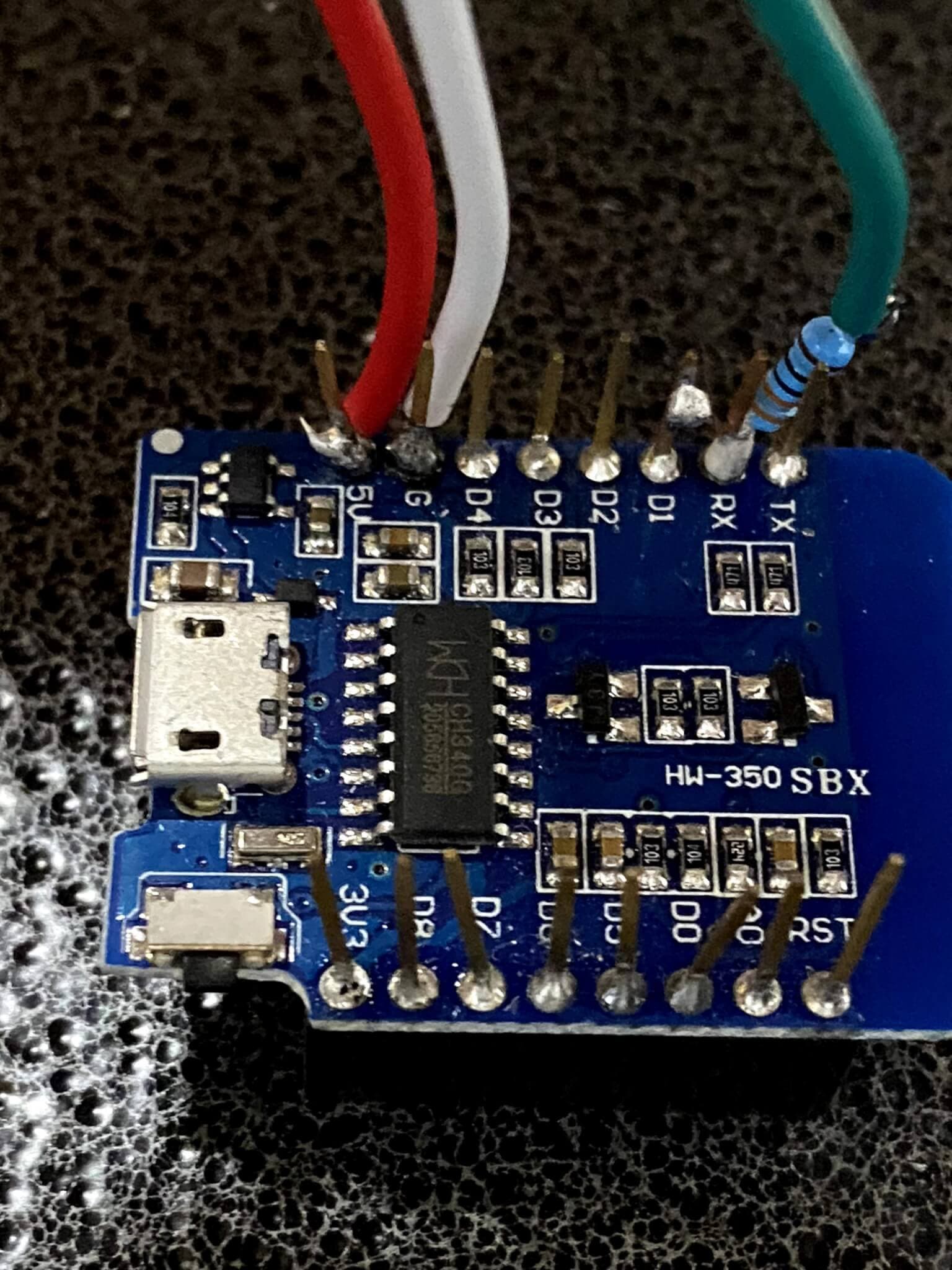
When daisy chaining strings or props ALWAYS make sure you also run a gnd parallel to the data between the end of one string/prop and the start of the next. It does not matter if they are already sharing a common ground.

Running this extra gnd with the data ensures that there are no small differentials between the data signal and ground from the last light on one string to the first of the next, and helps prevent glitches and flickering due to data corruption.

Ill stop after this final tip, as this is already a lot to take in, and may not even be of much use depending on the route you go with your setup. If you are going to be working with a lot of addressable LEDs get yourself a cheap but decent 1M bandwidth oscilloscope, it will make figuring out the cause of any potential data issue a lot easier!

2 Likes

I actually decided late last night/early this morning that i wanted to sneak another of April’s favorite prop into the show. I then proceeded to design it in autocad and cut it out on the CNC. Well 4 of them :rofl:

When I get to the wiring part I’ll try and remember to take some pictures of how i do my power convertors, injecting, and protect them from the rain etc for you guys.

2 Likes

Some images as promised, just a brief explanation for each as I need to finish programming the phenome maps and get these guys put out and added into the sequence.

Here is one of the cheapo dollar tree (10 for 1.25) containers in service as weatherproofing for a buck convertor. Same exact process for microcontroller protection.

Beginning of the prop, Data In (green) and GND in (white) have insulated spade connector for quick connection between props. Thinner white wire is gnd and thin blue is power in from the first buck convertor.,

Where two strings join together. The Power line has been cut from the connector so the power is not shared. GND and DATA are left connected between strings. Blue and white wire bring power and gnd from a second buck convertor to power string 2. The same is repeated with a new buck convertor per string (every 50 lights).

Back of the prop fully connected and wired up to 3 buck convertors,

And the result running a test pattern at 10% brightness…

4 Likes

@RRodman the pictures and explanation are ver much appreciated.

A question regarding the power injection.

Do you run a wire from each injection point all the way back to the power supplies? Or do you daisy chain from one injection point to the others?

If seperate runs could use shiw an image of it all coming back and connecting to the power supply?

Similar question with grounds. For the pixelblaze stuff they sall all grounds should be tied together. Is this the same for your setup? Again do you create runs all the way back to the power supply or daisy chain.

Apologies for the very noob questions. I have very limited experience trying to wire something like this up. Ive read and read and looked at lots of schematics. Ive about got my head wrapped around what the setup will be, but analysis paralysis kicks in and gets me chasing my tail.

My complete lack of experience and knowledge makes projects like this extra exciting given the wow factor of how things could go particularly wrong.

Thanks in advance. One day i hope to be able to setup half the light shiw you got there!

In a traditional setup where you are not using buck convertors, you can also daisy chain the power and gnd out to the injection points, you just need to keep an eye on the overall energy pull per circuit. I would also advise a fuse at every connection if directly connected to a power supply, that way if anything shorts or overloads you don’t fry out all your leds.

The biggest potential issue you will likely come across is ground loops. Do not allow a ground loop to be created or you can end up with major glitches due to an unstable gnd reference voltage.

Aside from that how gnd needs to work is the following. Controller and props driven by that controller need to share a common ground, powering them from the same source will give that common ground, but if using different power supplies for controllers and lights you will need to run a single wire between the controllers connecting the grounds. Beyond that the most important thing with the ground connection is that ANYWHERE a data line runs you need a GND run in parallel to ensure a proper reference.

o say you have a run of 10 props, the first 5 are on one power supply the second 5 are on another. Even with the two power supplies connected together via gnd you will still want to run a gnd line between each prop/string, again anywhere data travels you want a duplicate gnd traveling with it. Make sure they are coming from the end of the prop together, aka last light gnd and data out lines get extended to the next prop together, but the prop still gets its main power and gnd from the power supply.

Personal preference, AVOID 12V+ leds… There are multiple reports of led fires every year and they are ALWAYS using the 12V or higher leds. When the 5v go into meltdown at most they will give you a puf of magic smoke and maybe a very short lived flame if the water sealant manages to catch. I have no come across any reports of a fire being started by a 5v system.

1 Like

This topic was automatically closed 90 days after the last reply. New replies are no longer allowed.